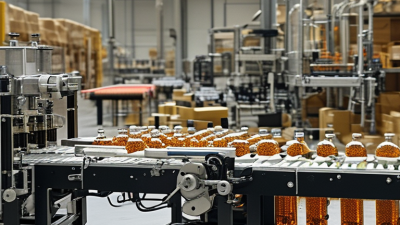
Choosing an automated packaging system is not simply a matter of buying the fastest machine. It means matching equipment to your product, package, production volume, and available floor space. A line handling glass jars needs different safeguards from one filling lightweight pouches. Even small details matter: changeover time, cleaning access, label accuracy, and how easily operators can reach a jammed conveyor.
Manufacturing pioneer Taiichi Ohno is often credited with the principle, “Without standards, there can be no improvement.” That idea is useful when evaluating automated packaging: document current cycle times, reject rates, and labor needs before comparing proposals. Ask suppliers to demonstrate your actual product and packaging materials, not just a similar sample. Watch a changeover. Check whether the system can connect with existing conveyors, printers, and inspection equipment. Get realistic figures for installation, training, maintenance, and spare parts.
The right choice depends on constraints as much as ambition. A high-speed system may be a poor fit if demand changes weekly or skilled maintenance support is limited. Start with the bottleneck you can measure, then assess whether automation addresses it. Be candid about what remains uncertain; supplier estimates are not operating results. Small trials help. A careful selection process can improve throughput, consistency, and traceability while reducing avoidable handling. The following guide explains the key questions to ask before investing—and the trade-offs worth examining twice.
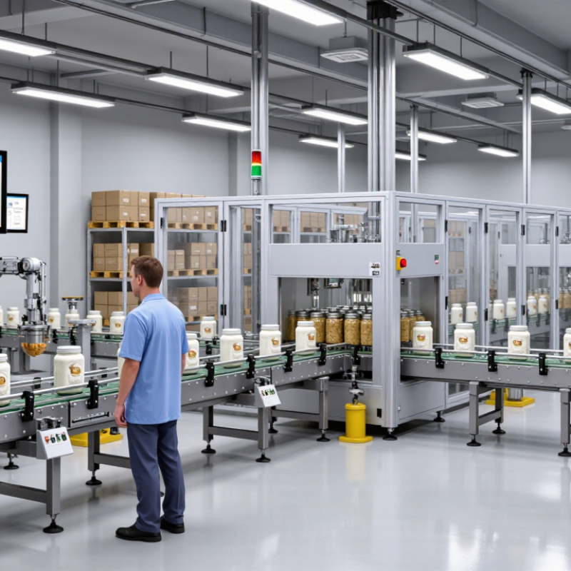
How to Choose an Automated Packaging System?
Define the Product, Pack Format, and Required Throughput in Units per Minute
Choosing an automated packaging system starts with the product, not the machine. Record its dimensions, weight, texture, and behavior during handling. A dry, rigid item may feed smoothly, while a soft or irregular product can shift, stick, or deform. Test actual samples, including the least consistent ones. That matters. Also note whether products arrive individually, in groups, or in bulk; feeding assumptions can quietly distort a proposal.
Define the finished pack: pouch, carton, tray, bottle, or another format. Specify dimensions, seal type, material, and how packs move downstream. A package that looks simple on a drawing may need careful alignment at the sealing station. Set throughput in units per minute, using saleable packs—not just machine cycles. Sixty packs per minute means little if changeovers, jams, or inspection reduce actual output. Include operating hours and peak demand, then request a trial with your product and packaging materials. Leave room for a learning curve. Estimates can feel precise while hiding assumptions. Check downtime, reject rates, and operator tasks; these details often change the practical number.
An automated packaging line’s nameplate speed is not its dependable output. Estimate good packs using OEE: availability multiplied by performance and quality, as described in Seiichi Nakajima’s Introduction to TPM (1988). The commonly cited 85% “world-class” benchmark combines approximately 90% availability, 95% performance, and 99.9% quality. A useful reference point. It is a target, not a guaranteed industry average. Product changes, cleaning cycles, minor jams, and staffing can all reduce real output.
Consider a line rated at 60 packs per minute during an eight-hour scheduled shift. Its theoretical output is 28,800 packs. At 85% OEE, estimated good output is 24,480 packs; at 65%, it is 18,720. That 5,760-pack difference may change which system fits your needs. Check that shift length and product mix reflect actual operations. Track downtime and rejects across several weeks, not just one strong day. Estimates can still miss changeover losses or upstream delays when teams define production time differently. Validate the calculation with a timed production trial before choosing line capacity.
Choosing an automated packaging system starts with the package, not the machine. A dry powder in a narrow pouch needs a different filling method from a thick sauce in a wide-mouth jar. Check product flow, target fill weight, and how the container behaves on a moving conveyor. A pouch that wrinkles under the sealing jaws can leak, even when the filler is accurate.
Match each module to the pack format. Auger fillers often suit powders; pumps can handle many liquids and pastes. For pouches, inspect seal width and temperature control. For jars, confirm the capper can apply steady torque without damaging closures. Labels need enough flat, clean surface to stay aligned. Case packers should accept the actual carton dimensions and loading pattern, not just a sample box. Small details matter.
Ask suppliers to run production-like samples, using your product and packaging materials. Watch for drips, skewed labels, slow changeovers, and cartons that need hand correction. These faults can be easy to miss during a short demonstration. Test real packs. Record results across several runs, including rejects and cleaning time. A line that looks efficient on paper may struggle when package sizes vary. I would leave room for adjustment; specifications rarely capture every awkward corner of daily production.
When choosing an automated packaging system, assess safety functions alongside speed, footprint, and output. ISO 13849-1 defines five Performance Levels: PL a, b, c, d, and e. They indicate increasing reliability for safety-related control functions. Higher is not automatically better.
Assess each task, such as clearing a jam, opening a guard, or cleaning near moving belts. Determine the required Performance Level, or PLr, for each safety function—not one level for the whole line. Then review the design category, component reliability (MTTFd), average diagnostic coverage (DCavg), and common-cause failure measures (CCF). The label alone proves little. A guard switch may stop one conveyor, while unsafe reset logic leaves another hazard active.
Request documented calculations and validation evidence showing that the achieved PL meets or exceeds each PLr. Test emergency stops, interlocks, and restart behavior under realistic faults, not only during a clean demonstration. Small details matter. A skewed carton may prompt repeated access to a guarded area, so safeguards must account for routine work. I would still question the assumptions: dust, washdown, maintenance habits, and later modifications can weaken an otherwise sound design.
When comparing automated packaging systems, verify the electrical design before focusing only on speed and output. IEC 60204-1 addresses machinery’s electrical equipment, starting at the supply connection point. Its scope includes rated supplies up to 1,000 V AC. It also specifies a 1,500 V DC limit and a frequency limit. This detail is easy to overlook in a throughput-focused quotation.
Ask for the declared supply rating, electrical diagrams, and the machine boundary used for the assessment. Check whether conveyor modules, printers, or other equipment have separate supplies. Those details may affect what the standard covers. No vague claims. A statement that equipment “meets IEC” is not enough without supporting documents. Review the design documentation and confirm the applicable edition with a qualified electrical professional.
A supply above 1,000 V AC does not mean safety requirements disappear. It means IEC 60204-1 alone may not address the full design. Do not assume. Ask which other standards and engineering assessments apply, and verify local adoption requirements. Keep the evidence. A clear scope review can reveal gaps early, though it may not answer every site-specific question.
Use this table as a preliminary selection checklist. IEC 60204-1’s voltage limit defines the standard’s scope; being within that limit does not, by itself, demonstrate conformity or establish that a machine is safe.
| Selection dimension | Example specification or check | Why it matters | Verification action |
|---|---|---|---|
| Rated supply voltage | Example: 400 V AC, three-phase | IEC 60204-1 covers machine electrical equipment with rated supply voltage not exceeding 1,000 V AC or 1,500 V DC. | Check the machine rating plate, electrical drawings, and supply requirements. Confirm the rated supply is within the applicable scope limit. |
| Supply frequency | Example: 50 or 60 Hz | The standard’s scope includes nominal supply frequencies not exceeding 200 Hz. | Confirm frequency compatibility for the machine and its electrical components; check the site supply before installation. |
| Control circuit voltage | Example: 24 V DC control circuits | Control voltage affects component selection, wiring, troubleshooting, and the integration of sensors and safety devices. | Review schematics and component ratings; confirm that control circuits are clearly identified and separated as required by the design. |
| Electrical load and capacity | Document the connected load, rated current, and expected operating conditions. | The supply and protective devices must be suitable for the machine’s actual electrical demand and installation conditions. | Compare the machine documentation with the facility supply capacity and have a qualified person verify protective-device coordination. |
| Prospective short-circuit current | Obtain the available fault-current value at the machine’s connection point. | Protective devices and the machine’s short-circuit withstand capability must be appropriate for the installation’s fault level. | Request the required upstream protection and short-circuit rating information; compare it with the site assessment. |
| Protective bonding and earthing | Check protective-earth connections for the frame, panels, and relevant exposed conductive parts. | A suitable protective-bonding arrangement helps reduce electric-shock risk under fault conditions. | Review the bonding diagram and verify connections and continuity during installation and commissioning. |
| Disconnecting means and isolation | Identify the supply disconnecting means and any separate energy sources. | Clear isolation arrangements support safe servicing and help prevent unexpected energization. | Check access, identification, isolation instructions, and how stored or auxiliary energy is controlled. |
| Emergency stop and safeguarding interfaces | Review emergency-stop devices, guards, interlocks, and safety-related control interfaces. | Packaging lines often combine moving conveyors, sealers, cutters, and other hazards; safety functions need risk-based design and validation. | Confirm the risk assessment, safety-function requirements, interface details, and validation records for the complete integrated line. |
| Installation environment | Consider washdown, dust, temperature, humidity, and chemical exposure. | Environmental conditions can affect enclosure selection, component life, and electrical reliability. | Specify the actual plant conditions and verify enclosure and component suitability with the machine documentation. |
| Documentation and commissioning | Obtain electrical diagrams, ratings, protection details, operating instructions, and test records. | Complete documentation supports safe installation, maintenance, fault-finding, and integration with other equipment. | Include document review and electrical verification in the acceptance and commissioning plan. |
Scope note: If the machine’s rated supply exceeds 1,000 V AC or 1,500 V DC, or its nominal supply frequency exceeds 200 Hz, do not assume IEC 60204-1 applies within its stated scope. Confirm applicable standards and requirements with a qualified electrical and machinery-safety professional.